 |
|
 |
How to Build Your Own PC - Save A Buck And Learn A Lot 9 Chapter 2: Component Overview 9 Case and Power Supply |
|


Matching Standoffs and Screws to Mainboard Holes
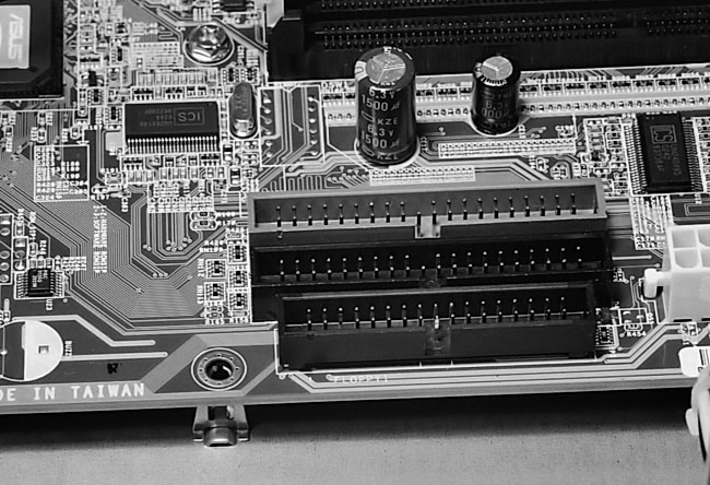
If you examine your mainboard, you’ll notice holes (see Figure 13). These holes are meant to line up with the standoffs in the case. The standoffs that don’t line up with holes can be removed. The purpose of the standoffs is to hold the bottom of the mainboard above the metal of the case. If the bottom of the mainboard were allowed to rest on the metal case directly, it’s possible the mainboard would short out and be damaged.
|
You’ll learn about static electricity in another section, but all sensitive electronic parts such as mainboards, PCI cards, and CPUs should be carefully handled to avoid damage from static electricity. Touch your hands to something metal to ground yourself before picking up your mainboard or CPU. This draws away any small charge that might remain on your hands so that it doesn’t zap a sensitive component.
Be sure to remove any extra standoffs that don’t match up with any holes in the mainboard. It’s possible that an extra and unnecessary standoff that doesn’t match up with any hole would improperly sit on the bottom of the mainboard shorting it out.
I’d count the number of holes in your mainboard and count the number of standoffs on the case and be sure the numbers are equal. Or, at least, have the number of holes exceed the number of standoffs. Then be certain that every standoff is visible through one of the holes in the mainboard. For example, if you’ve counted eight standoffs, your mainboard should have eight holes and all eight standoffs should be visible through the holes when the mainboard is seated.
You don’t need to place a standoff below every mainboard hole. But, be sure to place all the standoffs near where the ATX power supply, hard drive, and floppy drive cables will plug into the board. Figure 13 shows a standoff near the IDE and floppy connectors on the mainboard. It takes a bit of pressure to insert these cables, and you want the bottom of the mainboard supported in this region. You don’t want the mainboard to flex as you push in cables.
Some cheap cases and mainboards don’t match up as well as they should. But, usually, matching an ATX mainboard with an ATX case will work. If it doesn’t, it isn’t your fault. Blame the manufacturers for poor tolerances! And, you can always omit an offending standoff that just won’t line up with a mainboard hole. Your mainboard should attach to your case easily, as long as you’re matching an ATX case with an ATX mainboard.
If you examine the edge of one of the holes in the mainboard, you’ll notice a ring of metal around the hole. If a metal standoff is below and if a screw is used to secure the board to the standoff, that will properly ground the board to the case.
|
Home - Table Of Contents - Contact Us
How to Build Your Own PC (/byop/) on PCGuide.com
Version 1.0 - Version Date: May 4, 2005
Adapted with permission from a work created by Charlie Palmer.
PCGuide.com Version © Copyright 2005 Charles M. Kozierok. All Rights Reserved.
Not responsible for any loss resulting from the use of this site.