 |
|
 |
How to Build Your Own PC - Save A Buck And Learn A Lot 9 Chapter 4: Installing The Mainboard In The Case 9 Connecting Case Leads to the Mainboard |
|


Connecting Other Thin-Wire Connectors
Most of the leads, such as the power switch and the reset switch, can be connected in either orientation. There is no “Pin 1” or side to these connectors.
Otherwise, if connected in the wrong orientation, something just won’t work. For example, it’s possible to have the HD LED backward. If this is backward, when you start the PC, it’s likely your HD LED light won’t go on at all, or it will go on and stay on. Usually, we expect to see the HD LED on the front of the case blink with hard drive activity. However, these connectors, if oriented incorrectly, will not damage the system.
Figure 72 shows the connection of the reset switch.
|
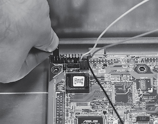
These connectors were discussed in the component overview section. It’s important to inspect the little pins carefully before installing your mainboard, because it’s easy to be off a pin and you’ll have a better view of the pins before the mainboard is installed.
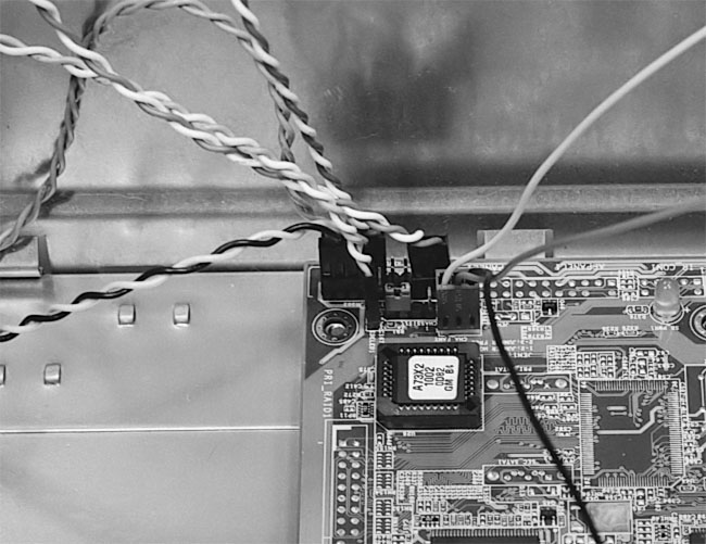
Figure 73 illustrates our mainboard with all of its thin-wire connections completed.
|
|
Home - Table Of Contents - Contact Us
How to Build Your Own PC (/byop/) on PCGuide.com
Version 1.0 - Version Date: May 4, 2005
Adapted with permission from a work created by Charlie Palmer.
PCGuide.com Version © Copyright 2005 Charles M. Kozierok. All Rights Reserved.
Not responsible for any loss resulting from the use of this site.