[ The PC Guide | Systems and Components Reference Guide | Hard Disk Drives | Hard Disk Interfaces and Configuration | Small Computer Systems Interface (SCSI) | SCSI Cables and Connectors ]
Narrow (50-Conductor) Single-Ended Cables, Connectors and Signals
Narrow cables are used for all narrow (8-bit) SCSI transfer modes. These are also sometimes called 50-conductor or 50-pin cables after the number of wires in the cable or pins in its connectors, respectively. They are also sometimes called SCSI-1 cables since the SCSI-1 standard only included narrow SCSI; this is not really a preferred way of naming cables however. Officially, narrow cables in the SCSI standards are called "A" cables. There are many different types of narrow cables, depending on the type of cable and connectors used. They are all collectively called "A" cables, though obviously just knowing that a particular cable is an "A" cable isn't enough to tell you if it is one you can use for your application.
Narrow SCSI uses 50 signals, carried on the 50 conductors in the cable. These are organized into 25 pairs of two wires each. For single-ended SCSI, each pair generally consists of a signal and a signal return, which is the same as a ground line. The signals are the same for the wires in all "A" cables, but the numbering of pins depends on the type of connectors used. Here are the signals and numbering conventions for narrow SCSI:
Signal |
Pin # |
Cable
Conductor |
Pin # |
Signal |
|||
Set 2 |
Set 1 |
Set 1 |
Set 2 |
||||
SIGNAL RETURN |
1 |
1 |
1 |
2 |
2 |
26 |
-DB(0) |
SIGNAL RETURN |
2 |
3 |
3 |
4 |
4 |
27 |
-DB(1) |
SIGNAL RETURN |
3 |
5 |
5 |
6 |
6 |
28 |
-DB(2) |
SIGNAL RETURN |
4 |
7 |
7 |
8 |
8 |
29 |
-DB(3) |
SIGNAL RETURN |
5 |
9 |
9 |
10 |
10 |
30 |
-DB(4) |
SIGNAL RETURN |
6 |
11 |
11 |
12 |
12 |
31 |
-DB(5) |
SIGNAL RETURN |
7 |
13 |
13 |
14 |
14 |
32 |
-DB(6) |
SIGNAL RETURN |
8 |
15 |
15 |
16 |
16 |
33 |
-DB(7) |
SIGNAL RETURN |
9 |
17 |
17 |
18 |
18 |
34 |
-P_CRCA |
GROUND |
10 |
19 |
19 |
20 |
20 |
35 |
GROUND |
GROUND |
11 |
21 |
21 |
22 |
22 |
36 |
GROUND |
(reserved) |
12 |
23 |
23 |
24 |
24 |
37 |
(reserved) |
(no connection) |
13 |
25 |
25 |
26 |
26 |
38 |
TERMPWR |
(reserved) |
14 |
27 |
27 |
28 |
28 |
39 |
(reserved) |
GROUND |
15 |
29 |
29 |
30 |
30 |
40 |
GROUND |
SIGNAL RETURN |
16 |
31 |
31 |
32 |
32 |
41 |
-ATN |
GROUND |
17 |
33 |
33 |
34 |
34 |
42 |
GROUND |
SIGNAL RETURN |
18 |
35 |
35 |
36 |
36 |
43 |
-BSY |
SIGNAL RETURN |
19 |
37 |
37 |
38 |
38 |
44 |
-ACK |
SIGNAL RETURN |
20 |
39 |
39 |
40 |
40 |
45 |
-RST |
SIGNAL RETURN |
21 |
41 |
41 |
42 |
42 |
46 |
-MSG |
SIGNAL RETURN |
22 |
43 |
43 |
44 |
44 |
47 |
-SEL |
SIGNAL RETURN |
23 |
45 |
45 |
46 |
46 |
48 |
-C/D |
SIGNAL RETURN |
24 |
47 |
47 |
48 |
48 |
49 |
-REQ |
SIGNAL RETURN |
25 |
49 |
49 |
50 |
50 |
50 |
-I/O |
![]() Note: "-P_CRCA"
was "-DB(P0)" (parity zero) before the introduction of CRC.
Note: "-P_CRCA"
was "-DB(P0)" (parity zero) before the introduction of CRC.
"Woah, woah, what are all those numbers, shouldn't it just be one number per signal?" Nothing's simple with SCSI, unfortunately, so let's see if I can explain this table. The table is double-width to prevent its length from getting excessive, and is "mirror-imaged" to make the data easier to understand and to show how the wires are "paired". On the outside are the signal names. Notice that all the "real signals" are on the right-hand side, and the "signal returns" and grounds are on the left. The middle two columns show the conductor numbers assigned to each signal; these are the numbers of the wires in the cable. The numbers between those two columns and the signal names represent two different sets of pin number assignments, which are used for different connector types in the SCSI standards. "Set 1" is the same as the conductor numbering; since the numbers alternate, this means that consecutive numbers are "pairs"; #1 and #2, #3 and #4 and so on, to #49 and #50. "Set 2" instead numbers going down the left column and then does the right column.
This table shows which connector types use which numbering schemes (see the page on connector types for help in making sense of the terms below):
Connector Alternative |
External Cables |
Internal Cables |
||
Connector Type |
Pin Set Number |
Connector Type |
Pin Set Number |
|
"Alternative 1" |
High Density |
2 |
High Density |
2 |
"Alternative 2" |
Centronics |
1 |
Regular Density |
1 |
This means that the older cable styles--Centronics for external and regular density for internal--have the pin numbers the same as the conductor numbers. Cables using the newer, high density connectors--for both internal and external cables--use the different numbering specified as "Set 2". I really do not know what the reason was for this change, though I would guess that it made attaching the connectors easier somehow.
OK, now I probably have you more confused than ever. Let's dig past all these formalities and talk about practical "A" cables. These are the most common types of "A" cables that are used in real SCSI systems in the PC for narrow, single-ended implementations:
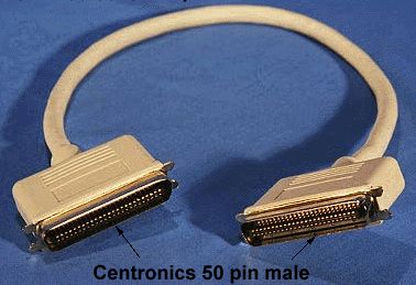
- External Centronics "A" Cables: These are the oldest common type of external SCSI cables, using Centronics-style ("Alternative 2") connectors. They connect older external devices to narrow SCSI buses.
- External High Density "A" Cables: These cables are used for newer external devices that have high density ("Alternative 1") connectors instead of Centronics connectors.
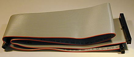
- Internal Regular Density "A "Cables: Flat, 50-conductor ribbon cables using the older "regular density" ("Alternative 2") connectors. Widely used for connecting to older hard disks and slower devices such as CD-ROMs.
- Internal High Density "A" Cables: 50-conductor ribbon cables using the newer high density ("Alternative 1") connectors are used for newer or faster devices (though most of these are now wide devices, and so use wide cabling.)
|
An external, male Centronics "A" cable
(above) and a female |
Original images � Computer Cable Makers, Inc. |
To a great extent, the choice of cable depends on the connectors used on the host adapter and the devices being considered. There are some cables that have two different connector types on them, for special applications.There are also a myriad of adapters to allow different connector types to be attached to the same cable.
![]() Next: Wide (68-Conductor) Single-Ended Cables, Connectors and Signals
Next: Wide (68-Conductor) Single-Ended Cables, Connectors and Signals
| The PC Guide
(http://www.PCGuide.com) Site Version: 2.2.0 - Version Date: April 17, 2001 © Copyright 1997-2004 Charles M. Kozierok. All Rights Reserved. |
Not responsible for any loss resulting from the use of this site. Please read the Site Guide before using this material. |