[ The PC Guide | Systems and Components Reference Guide | Hard Disk Drives | Hard Disk Interfaces and Configuration | Integrated Drive Electronics / AT Attachment (IDE/ATA) Interface | IDE/ATA Configuration and Cabling ]
Ultra DMA (80-Conductor) IDE/ATA Cables
There are a lot of issues and problems associated with the original 40-conductor IDE cable, due to its very old and not very robust design. Unterminated flat ribbon cables have never been all that great in terms of signal quality and dealing with reflections from the end of the cable. The warts of the old design were tolerable while signaling speeds on the IDE/ATA interface were relatively low, but as the speed of the interface continued to increase, the limitations of the cable were finally too great to be ignored.
In the ATA/ATAPI-4 standard that introduced the Ultra DMA transfer mode set, a new cable was introduced to replace the old standby: the 80-conductor IDE/ATA cable. The name is important: the new cable has 80 conductors (wires)--it does not have 80 pins on each connector, though, just 40. This means that the new cable is pin-compatible with the old drive. No change has been made to the IDE/ATA connectors, aside from the color-coding issue (see below).
The obvious question, of course, is this: what's the point of adding 40 extra wires to a cable if they aren't connected to anything? :^) Well for starters, the 40 wires are connected to something, just not their own pins on the interface connectors. The extra 40 wires don't carry new information, they are just used to separate the "real" 40 signal wires, to reduce interference and other signaling problems associated with higher-speed transfers. So the 40 extra conductors are connected to ground, interspersed between the original 40 conductors of the old cable. Any stray signals that would "cross-talk" between adjacent wires on the 40-conductor cable are "absorbed" by these extra ground wires, improving signal integrity. The extra ground wires can be either all of the even-numbered wires, or all of the odd-numbered wires in the cable.
There are a number of other attributes and characteristics of the 80-conductor cable, which I'm going to list in bullet form for easier absorption:
- Requirement: The 80-conductor cable was first defined with the original Ultra DMA modes 0, 1 and 2, covering transfer speeds up to 33.3 MB/s. The cable is considered "optional" for those modes. However, for any Ultra DMA modes above mode 2, the 80-conductor cable is mandatory.
- Detection: Since the cable is mandatory for high-speed modes, the system has to have some way of knowing it is installed. This is done by having the /PDIAG:/CBLID signal, carried on pin #34 of the interface, grounded in the connector that attaches to the motherboard. Since the older 40-conductor cable would not have this pin grounded, by looking for the grounding on this pin at startup the host can determine if the 80-conductor cable is installed.
- Cable Select Support and Drive Assignment: All 80-conductor cables that meet the ATA specifications support the cable select feature automatically. This is accomplished by special connection of the CSEL signal on pin #28. The cable can still be used with drives that have been manually configured as master or slave, of course. See the discussion of cable select for more.
- Connector Assignments and Color Coding: For the first time, the
80-conductor cable defines specific roles for each of the connectors on the cable; the
older cable did not. Color coding of the connectors is used to make it easier to determine
which connector goes with each device:
- Blue: The blue connector attaches to the host (motherboard or controller).
- Gray: The gray connector is in the middle of the cable, and goes to any slave (device 1) drive if present on the channel.
- Black: The black connector is at the opposite end from the host connector and goes to the master drive (device 0), or a single drive if only one is used.
There are a couple of reasons why this coding was done. The main one is the issue mentioned in the discussion of the 40-conductor cable: it is not a good idea to connect a single drive to the middle connector on a ribbon cable, because the "stub" of left-over, unconnected cable causes signaling problems. With Ultra DMA this "stub" connection is not just "not recommended", it is illegal: a single device must be at the end of the cable. The other reason is that since these cables support cable select inherently, the position of each drive on the cable matters if cable select is being used. With these two needs combined, it just made sense to design the cable so that drive positioning was explicitly clear.
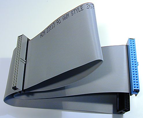
|
A standard 80-conductor Ultra DMA IDE/ATA interface
cable. |
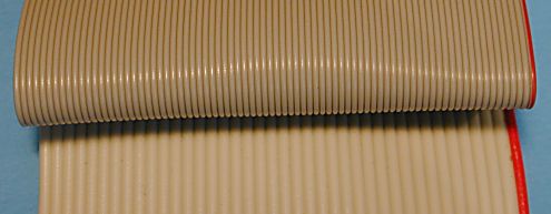
- Width: Despite the extra 40 wires, the 80-conductor cable is about the same width as a 40-conductor cable--which is good, because the current width is difficult enough to work with. :^) This bit of "magic" is accomplished by using thinner, lower-gauge wires within the cable.
|
A comparison of the wires used in 80-conductor and
40-conductor cables. |
Aside from the above, the cable can be treated the same way as a 40-conductor cable. Since it is of higher quality, it can be used in place of a 40-conductor cable in older systems without any issues. However, it does not directly replace a 40-conductor cable select cable. Note also that the 18" length restriction associated with the original 40-conductor cable applies to this variation as well.
![]() Next: Notebook IDE/ATA Configuration
Next: Notebook IDE/ATA Configuration
| The PC Guide
(http://www.PCGuide.com) Site Version: 2.2.0 - Version Date: April 17, 2001 © Copyright 1997-2004 Charles M. Kozierok. All Rights Reserved. |
Not responsible for any loss resulting from the use of this site. Please read the Site Guide before using this material. |