[ The PC Guide | Systems and Components Reference Guide | Hard Disk Drives | Hard Disk Interfaces and Configuration | Integrated Drive Electronics / AT Attachment (IDE/ATA) Interface | IDE/ATA Configuration and Cabling ]
Notebook IDE/ATA Configuration
Notebook PCs are very similar to desktop PCs in terms of overall architecture, but very different in implementation. Hard disks and hard disk interfaces are certainly no exception to this general rule of thumb. Virtually all notebooks have built-in hard disks using the IDE/ATA interface, but the way they are actually connected the machine is not the same as for desktop PCs.
Hard disks are installed in notebooks in two very different ways--which method is used on a particular model depends on the decisions made by the engineers that created it. The first is a proprietary installation, where the hard disk is just rammed "in there somewhere"; the second is an open or removable installation. The differences between the two are pretty obvious. If a notebook has a proprietary hard disk installation, it probably still uses the regular IDE/ATA interface, but the drive is attached using special cables and connectors, and is not intended to be touched by the user. Needless to say, this is a very inflexible arrangement, because if you ever need or want to replace or upgrade the drive, you have to refer to qualified service personnel for service. This was the most common way of putting hard disks into notebooks during their early years.
Most modern hard disks today use the open arrangement; unlike the proprietary installations these are probably easier to install and remove than the hard disks in a regular PC! A typical hard disk will use a special hard disk bay that has room for a standard, 2.5" form factor hard disk. Bays differ between models, especially in terms of the height of the drive, but the form factor itself is pretty much standardized at this point; you can read more about it here. The advantages of a standard interface are obvious: interchangeability and competition (allowing you choices between drive makers).
The usual method of attachment of notebook hard disks is through a special 44-pin connector that includes all of the signals needed by the drive, instead of the usual 40-pin data connector and 4-pin power connector. This provides the basis for allowing the drives to be quickly and easily removed and replaced. The drive itself uses a regular set of straight pin connectors, just like a desktop drive. Since these pin connectors are not well-suited for easy insertion and removal from a notebook, the drive is mounted into a special carrier or "caddy". This device includes as part of its hardware an adapter which converts the regular pins into a single connector designed for drive swapping. The technique used for this attachment is very similar in concept to the SCA connectors used for some types of SCSI drives (though the two are obviously very different in all but this concept.)
The first 40 signals on a notebook's connector are the same as those of the regular 40-pin connector; the additional four signals are defined as follows:
Pin # |
Signal |
Pin # |
Signal |
41 |
+5 V (logic) |
42 |
+5 V (motor) |
43 |
GROUND |
44 |
(reserved) |
You may immediately notice that there is no +12 V connection as exists for regular drives, because 2.5" form factor drives have 5-volt motors. Two separate +5 lines are provided; one for the motor and the other for the hard disk's circuit board.
|
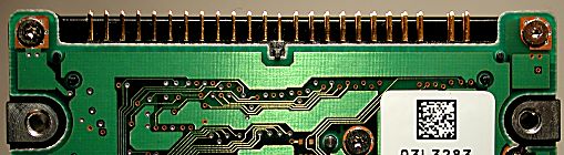
Underside of a 2.5" form factor notebook hard
drive. |
Notebooks are of course very limited in space, so "expansion" is usually not an option, at least not using the built-in IDE/ATA interface. The hard disk usually is assigned as the single device on the primary IDE/ATA channel, and the drive's optical drive (if any) assigned to the secondary. There's no way to decide to add a second device to these channels on a typical notebook. Expanding a notebook to add a second hard disk is usually done using one of the specialty interfaces such as USB or PCMCIA.
![]() Next: Independent Master/Slave Device Timing
Next: Independent Master/Slave Device Timing
| The PC Guide
(http://www.PCGuide.com) Site Version: 2.2.0 - Version Date: April 17, 2001 © Copyright 1997-2004 Charles M. Kozierok. All Rights Reserved. |
Not responsible for any loss resulting from the use of this site. Please read the Site Guide before using this material. |