 |
|
 |
How to Build Your Own PC - Save A Buck And Learn A Lot 9 Chapter 6: Connecting Components 9 Connecting the Ribbon Cables |
|


The Floppy Ribbon Cable
With bootable CD drives today and the limited capacity of floppies, they’re not used very often. But, they can be useful for creating an emergency boot disk. And, if you have a case, such as the Enlight case for this build, with a hole for a floppy, it’s probably good to have something installed behind the floppy hole, because someone will eventually try to insert a floppy disk. Plus, for $15, a floppy is inexpensive.
The floppy drive is connected with the 34-pin ribbon cable (Figure 2) which comes with your mainboard. It won’t plug into the forty-pin socket used for the hard drive and CD-RW drive. There’d be pins left over.
If you examine one end of the floppy cable connector, you’ll see that there is a single hole missing in the connector. If I recall right from math, a negative times a negative is a positive. So, lack of a hole means material still remains. The other end of the cable is also missing a hole. This missing hole can be matched with a missing pin (on a drive or mainboard) to help orient the connector.
There is also sometimes a protruding notch on one side of each connector at the top and outside part of the connector. This notch will match up with a notch in the mainboard floppy socket. This helps to assure the ribbon cable is installed in the proper orientation. Sometimes, your ribbon cable will also have a red stripe down one side. Red means Pin 1. Or, sometimes, there will be something else, such as a red triangle, showing Pin 1. Pin 1 will be noted in your mainboard manual.
Find the 34-pin floppy connector on your mainboard (Figure 91). When in doubt, consult the mainboard manual. Examine the pins carefully. You’ll see there is a missing pin. That’s normal. It will match up with the lack of a hole in the ribbon connector. Be careful not to force a connector in the wrong orientation, or you might damage or bend a pin.
|
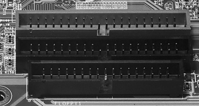
You’ll also see a cut-out notch on one long side of the socket. This is designed to help assure proper orientation of the floppy cable. However, some cables don’t have notches. So, sometimes the cut out isn’t much help.
If there is a notch on the cable, use it to determine the proper orientation of the cable. If your cable has no notch, either match up the missing hole with the missing pin, or else use your mainboard manual to determine Pin 1 of the floppy connector and match that to the red stripe of the floppy cable. One way or another, you’ll get that sucker installed in the proper orientation.
Similarly, the floppy drive itself is missing one pin on the connector, so you can use that as a guide for the proper orientation of the cable to the drive. Other floppy drives have Pin 1 marked in some other way. Pin 1 always goes to the red line side of the cable. And, if you really must confirm orientation yet another way, you can do a search on google for your particular floppy drive to find a manual for your floppy or more information about it. Most floppy drives don’t come with any documentation.
|
Home - Table Of Contents - Contact Us
How to Build Your Own PC (/byop/) on PCGuide.com
Version 1.0 - Version Date: May 4, 2005
Adapted with permission from a work created by Charlie Palmer.
PCGuide.com Version © Copyright 2005 Charles M. Kozierok. All Rights Reserved.
Not responsible for any loss resulting from the use of this site.