 |
|
 |
How to Build Your Own PC - Save A Buck And Learn A Lot 9 Chapter 6: Connecting Components |
|


Connecting the Sound Cable
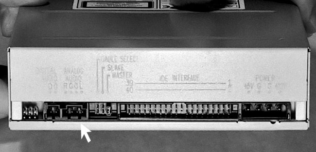
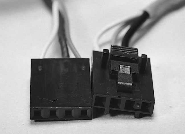
Examining the back of the CD-RW (Figure 88) we also see there is a connector for a sound cable (Figure 89).
|
|
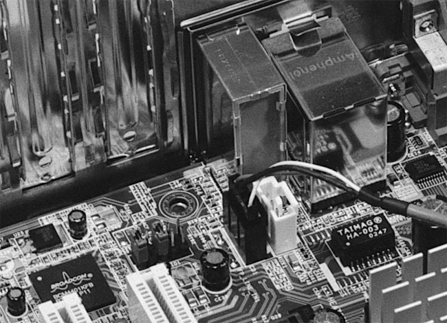
The other end of this cable will connect to the mainboard if you have built-in sound (Figure 90) or to a sound card.
|
The instructions for the CD-RW say that the cable can only be plugged in one way. And, a sound cable is included. But, examining the cable, we see they lied (see Figure 89). It can be plugged in two ways. Some sound cables can be plugged in only one way, because they have notches in them which identify the top. Others are just flat little suckers that will go in in either direction.
If your CD’s sound doesn’t work, try reversing the cable, if you have a flat, notchless connector. It should work in either orientation, however, because the four pins are usually denoted RGGL, right speaker, ground, ground, and left speaker. Right is often red in color. If a device doesn’t work, always check to see that it’s properly connected.
Sometimes instructions for PC components, such as CD-RWs, make little sense, because the instructions don’t seem to match up with the actual device you’re holding. Sometimes the instructions were written and a vendor was changed and the components changed, but the instructions weren’t updated. This can happen with software also.
|
Home - Table Of Contents - Contact Us
How to Build Your Own PC (/byop/) on PCGuide.com
Version 1.0 - Version Date: May 4, 2005
Adapted with permission from a work created by Charlie Palmer.
PCGuide.com Version © Copyright 2005 Charles M. Kozierok. All Rights Reserved.
Not responsible for any loss resulting from the use of this site.