[ The PC Guide | Systems and Components Reference Guide | Hard Disk Drives | Construction and Operation of the Hard Disk | Hard Disk Connectors and Jumpers ]
Data Interface Connector
Modern hard disk drives use one of two interfaces: IDE (ATA) and its variants, or SCSI. You can tell immediately by looking at the back of the hard disk which interface is being used by the drive:
- IDE/ATA: A 40-pin rectangular connector. See here for more information on IDE/ATA cables and connectors.
- SCSI: A 50-pin, 68-pin, or 80-pin D-shaped connector (the same shape used for serial and parallel port connectors). A 50-pin connector means the device is narrow SCSI; 68 pins means wide SCSI; 80 pins means wide SCSI using single connector attachment (SCA). See here for more on SCSI cables and connectors.
|
A standard hard disk IDE/ATA data interface connector. |
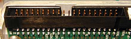
The connectors on hard disk drives are generally in the form of a 2xN rectangular grid of pins (where N is 20, 25, 34 or 40 depending on the interface). Older ST-506 (also called MFM, RLL) and ESDI hard disks used two data connectors, one 34 pins and the other 20 pins. These connectors were often not in the form of pins but rather card edge connectors, such as those used by ISA expansion cards. Some SCSI connectors may have different shapes, especially older ones.
While most current SCSI interface connectors are keyed to prevent incorrect insertion (because they are D-shaped), this is not always the case for other interfaces. For this reason, it is important to make sure that the cable is oriented the correct way before plugging it in. The cable has a red stripe to indicate wire #1 and the hard disk uses markers of one form or another to indicate the matching pin #1.
![]() Next: IDE/ATA Configuration Jumpers
Next: IDE/ATA Configuration Jumpers
| The PC Guide
(http://www.PCGuide.com) Site Version: 2.2.0 - Version Date: April 17, 2001 © Copyright 1997-2004 Charles M. Kozierok. All Rights Reserved. |
Not responsible for any loss resulting from the use of this site. Please read the Site Guide before using this material. |