[ The PC Guide | Systems and Components Reference Guide | Hard Disk Drives | Hard Disk Interfaces and Configuration | Integrated Drive Electronics / AT Attachment (IDE/ATA) Interface | IDE/ATA Configuration and Cabling ]
IDE/ATA Connectors and Signals
Standard IDE/ATA hard disks and ATAPI devices use two different connectors. The first is the data connector, to which the IDE/ATA cable attaches. The second is the power connector, which comes from the power supply, and of course, provides power to the drive. The power connectors are standardized and discussed in more detail in this construction page, and this power supply page. The data connectors and signals I will describe below.
Let's begin with the signals themselves. There are 40 wires in a regular IDE/ATA cable, so it's no surprise that there are 40 corresponding signals. (Incidentally, the newer 80-conductor cable uses the same pins and signals. For compatibility, and because the 40 extra conductors that were added are just grounds, the pin assignments are the same.) The table below lists the names of the signals, along with the pin number of the standard connector that each uses:
Pin # |
Signal |
Pin # |
Signal |
1 |
-RESET |
2 |
GROUND |
3 |
DD7 |
4 |
DD8 |
5 |
DD6 |
6 |
DD9 |
7 |
DD5 |
8 |
DD10 |
9 |
DD4 |
10 |
DD11 |
11 |
DD3 |
12 |
DD12 |
13 |
DD2 |
14 |
DD13 |
15 |
DD1 |
16 |
DD14 |
17 |
DD0 |
18 |
DD15 |
19 |
GROUND |
20 |
(key) |
21 |
DMARQ |
22 |
GROUND |
23 |
-DIOW: STOP |
24 |
GROUND |
25 |
DIOR:-HDMARDY:HSTROBE |
26 |
GROUND |
27 |
IORDY:-DDMARDY:DSTROBE |
28 |
CSEL |
29 |
-DMACK |
30 |
GROUND |
31 |
INTRQ |
32 |
(reserved) |
33 |
DA1 |
34 |
-PDIAG:-CBLID |
35 |
DA0 |
36 |
DA2 |
37 |
-CS0 |
38 |
-CS1 |
39 |
-DASP |
40 |
GROUND |
(For a general description of what signals are, and what the "dash" ("-XXX") notation means, see this page.)
Now, I'm not going to describe all of these signals in detail; if you are interested in learning all about them, you should order the latest IDE/ATA standard and read up all about the signaling. However, I do have a few explanatory notes:
- Pins 3 through 18: These are the 16 data lines used for transferring data over the interface.
- Pin 20: This is a "key" location, used for orientation; see below for more.
- Pin 28: This is the cable select signal used for cable select operation.
- Pin 32: This was once known as "/IOCS16" but is not currently used.
- Pin 34: This pin is used (in part) to detect the presence of an 80-conductor IDE/ATA cable for Ultra DMA operation; see here for more.
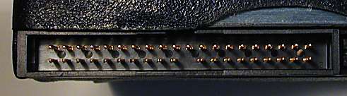
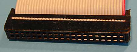
The data connectors for IDE/ATA are standardized. Drives and hosts (controllers) have male connectors consisting of two rows of 20 pins, with a plastic "fence" surrounding them. Cables have female connectors with two rows of 20 holes for the pins. There are two ways that these connectors are supposed to be keyed for proper orientation (to prevent the cable from being inserted into the drive or controller upside-down). On the male connectors, pin #20 is supposed to be missing, and on the cable, the hole for pin #20 is supposed to be blocked. Also, the female (cable) connectors are supposed to have a tab in the middle on top that matches a gap in the plastic surrounding the male pins. If you tried to put a cable in upside-down, these keyings would prevent insertion.
Unfortunately, yet again, these measures were never standardized. Some drives and controllers were produced that had pin #20 in place, even if it was not used, and some did not have the "gap" in the plastic surrounding the pins. If you used a properly-designed cable with an improperly-constructed drive or controller, the cable wouldn't fit. To avoid this, many IDE/ATA cable makers just said "to heck with it" and made the cables with no plastic tab on the connectors, and no block for hole #20. As a result, the entire orientation scheme fell apart, so one must be careful to line up pin #1 on the cable with pin #1 on the drive. There is usually a red stripe on the edge of the cable on the side where pin #1 is, but it's still easy to get the cable backwards. Fortunately, the standard data connector has no live power signals, so damage is not typical if the cable is inserted upside-down (though the drive won't work that way, of course!)
|
An IDE/ATA interface connector on a hard disk (above)
and on a |
![]() Note: The 2.5" form
factor drives used in notebook PCs use different connectors and are attached differently. See this page for details.
Note: The 2.5" form
factor drives used in notebook PCs use different connectors and are attached differently. See this page for details.
![]() Next: Standard (40-Conductor) IDE/ATA Cables
Next: Standard (40-Conductor) IDE/ATA Cables
| The PC Guide
(http://www.PCGuide.com) Site Version: 2.2.0 - Version Date: April 17, 2001 © Copyright 1997-2004 Charles M. Kozierok. All Rights Reserved. |
Not responsible for any loss resulting from the use of this site. Please read the Site Guide before using this material. |